AS5145
12-Bit Programmable Magnetic Rotary Encoder
The AS5145 is a contact less magnetic rotary encoder for
accurate angular measurement over a full turn of 360 degrees.
It is a system-on-chip, combining integrated Hall elements,
analog front end and digital signal processing in a single device.
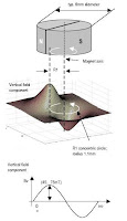
To measure the angle, only a simple two-pole magnet, rotating
over the center of the chip, is required. The magnet may be
placed above or below the IC.The absolute angle measurement
provides instant indication of the magnet’s angular position with
a resolution of 0.0879º = 4096 positions per revolution. This
digital data is available as a serial bit stream and as a PWM
signal.An internal voltage regulator allows the AS5145 to
operate at either 3.3V or 5V supplies.
Typical magnet (6x3mm) and magnetic field distribution
Daisy Chain Mode
The Daisy Chain mode allows connection of several
AS5145’s in series, while still keeping just one digital input
for data transfer (see “Data IN” in Figure 9). This mode is
accomplished by connecting the data output (DO; pin 9) to
the data input (PDIO; pin 8) of the subsequent device. The
serial data of all connected devices is read from the DO pin
of the first device in the chain. The length of the serial bit
stream increases with every connected device,
it is n * (18+1) bits: n= number of devices. e.g. 38 bit for two
devices, 57 bit for three devices, etcetc.