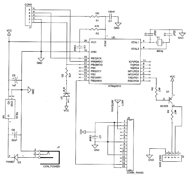
Download : schematic, verilog source code, uip port
tag : AVR, Project, WLAN, Data Transfer, Wireless Project, Microcontroller Design (src)
Microchip provides Microcontroller and Analog Semiconductors, with low-risk product development, lower total system cost and faster time to market.
|
||||
---|---|---|---|---|
|
||||
---|---|---|---|---|
Download
Source and PDF
These IC’s and the Avago galvanic isolators are truly the "enabling technology" for this project. The controller IC is also used to perform system health checks, and set the operating points of the individual vacuum tubes. This allows total system programmability, offering several possible preset operating modes.
Download
Project Documentation
Remote controls usually consist of encoder/decoder parts connected to a transmitter/receiver module which takes care of the transmission of digital signals by radio or infra waves. The format of this project's signal is designed to be ideal even for the cheapest ASK RF modules (using 50% signal/silence ratio), and it is similar to the Philips RC-5 format used in infrared remote controls. The transmitter has a varying number of buttons and sends the states of these inputs to the receiver. The receiver device decodes the message and sets the outputs accordingly.
Download schematic IR(jpeg), schematic RF
source
Among the Amateur Radio fraternity, a device such as the one described here would otherwise be known as a Field Strength Meter (FSM). Its main purpose would be to check that RF power is being radiated from a transmitting antenna. Some FSMs are tuneable across a wide range of frequencies, which allows the device to work with different transmitters and antennae - usually from HF to VHF and beyond. A difference with this unit is that it is only sensitive to those signals in the R/C section of the radio spectrum. The on-board trimmer allows you to tweak for maximum signal strength of your frequency of choice, whether it be 27MHz AM, or 40MHz FM.
In order to read the received signal strength, such a unit would ordinarily employ a mechanical analogue meter. The unit described here differs in that it uses four super-bright LEDs. The benefit of this is that it allows you to read the display from a distance - even in bright sunlight.
Download schematic(gif), PCB1, PCB2
The sensor array consists of 4 touch sensors on the bottom of each foot, Left and right IR obstacle detection, and 4 CdS photo detectors located on all four sides of the robot. The heart of the control system is a Microchip PIC16F819 micro-controller and a separate 8 channel A-D converter.
The mechanical structure is built from brass tubing (which all the wiring runs through, UHMW (a high density plastic material), and PCBs. Perhaps the most striking aspect of the robot is the use of PCBs to create a 3D structure and mount all of the circuits/electronics.
tag : robotic design,PIC, Microcontroller, Electronic (src)
There are actually two PIC16F84's on the hexapod. The main processor contains all of the walking code and generates positioning pulses for all 12 servos. Twelve of the 13 I/O lines are used for switch inputs - one on the bottom of each foot and a contact sensor in the front of each leg. The servo pulses are output sequentially on the last I/O line. All the second processor does is de-multiplex the pulses from the main processor and send them to the appropriate servo
tag : Robotic, PIC16F84 Project, Electronic Design, Microcontroller Project (src)
Mike Davey, the designer, said that the system was built as a number of modules to make design and trouble shooting simpler. The most complex of the modules is the inkjet system. At the center of the inkjet module is a spindle that rotates the wooden nickel under the inkjet head. This spindle is turned with a stepper motor and allows for repeatable placement of the nickel under the inkjet head. The spindle is also moved horizontally under the inkjet head by a second stepper motor coupled to a lead screw and slide mechanism. A Propeller Chip controls all the elements of the inkjet module. The Propeller Chip was chosen for the inkjet system for two reasons. The first is that the inkjet required fast and accurate timing. The Propeller Chip has direct control over the inkjet head through a simple Darlington transistor array. Each of the inkjet's 12 nozzles needs pulsed on for no more than 6 microseconds. The second reason the Propeller Chip was chosen is that the module needed at least 24 IO pins to control the inkjet module. The inkjet head needs 12 pins, the two steppers need 4 pins each, there are three IR sensors, and I needed at least one pin to communicate with the BASIC Stamp 2.
Download :
Source code
Download program and free servo controller here
Make sure you have read the license conditions, and that you agree with them, before downloading any files. Hardware Schematic page 1 Schematic page 2 Schematic page 3 Board (Eagle format) Software Program file. Version 1.00 Source in AVR assembler. Version 1.00 Documentation User manual One-page menu overview
Feature list:
Download :
See the robot in action
via circuitlake
Visual Analyzer is a free software oscilloscope. They describe it as "A complete professional real time software that transforms your PC into a complete set of instruments. No new hardware is necessary (you can use the Sound Card of your PC)."
Read more and download it click here
the PIC. Some of the topics included are:
* Simple use of MPASM assembler
* Demonstration of use of timer 0 and the prescaler
* Use of length of instructions to set up timing delays
* Using interrupt routines
* Detection of switch closures including debouncing
* Saving and recovering data from the onboard EEPROM
Download the source code (.asm)
[source]
|
---|