
Fortunately, the default is set to LCD type 16*2. This is the most common LCD with two lines and 16 characters per line. HD44780 type LCD's have eight datalines, but they can be controlled in a more economical way by using the four 'upper' lines. This saves four i/o pins on your controller. This is the default (4-bit bus mode) in the options window. Sending data in the 4-bit bus mode of course takes two writes for each 8-bits to send. If you really need the LCD to be as fast as possible (and you seldom do) you will have to choose the 8-bit bus mode.
source : qsl.net
BattMan II is a computer controlled battery manager, intended for typical rechargeable batteries used by R/C and electronics hobbyists, as well as various consumer product batteries.
BattMan II has the following capabilities:
- Works with Nickel-Cadmium (NiCd), Nickel-Metal-Hydride (NiMH), Lithium-Ion (Li-Ion), Lithium-Polymer (LiPo), Lithium-Nano-Phosphate (LiNP), and Lead-Acid (Pb-Acid) batteries of 1.2 to 14.7 Volts.†
- Discharges batteries to measure capacity at rates of 130mA to 2A.
- Charges at rates of 130mA to 1.3A.†
- Automatically performs repeated discharge/charge cycles to break in new batteries, or erase NiCd voltage depression in old ones.
- Measures internal resistance.
- Monitors self-discharge.
- Real time graphical display lets you see problems like mismatched cells.
- Keeps a log of all operations performed, which can be imported into any spreadsheet program.
- Saves graphs of charge, discharge, auto-cycle, and monitor operations.
- Connects via parallel port to any PC running Microsoft Windows (95, 98, ME, 2000, XP, or Vista).
- Operating software, complete with source code, is available to download.
Download schematic and software
releated search: Electronic Circuit Project, Battery manager (src)
The Arduino Duemilanove ("2009") is a microcontroller board based on the ATmega168 (datasheet). It has 14 digital input/output pins (of which 6 can be used as PWM outputs), 6 analog inputs, a 16 MHz crystal oscillator, a USB connection, a power jack, an ICSP header, and a reset button. It contains everything needed to support the microcontroller; simply connect it to a computer with a USB cable or power it with a AC-to-DC adapter or battery to get started.
Download : Eagle Files (zip) and Schematic (PDF)
related search : Microcontroller Board, Arduino, ATmega168 (src)
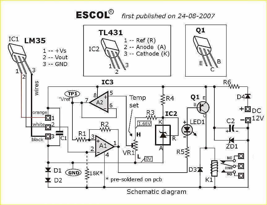
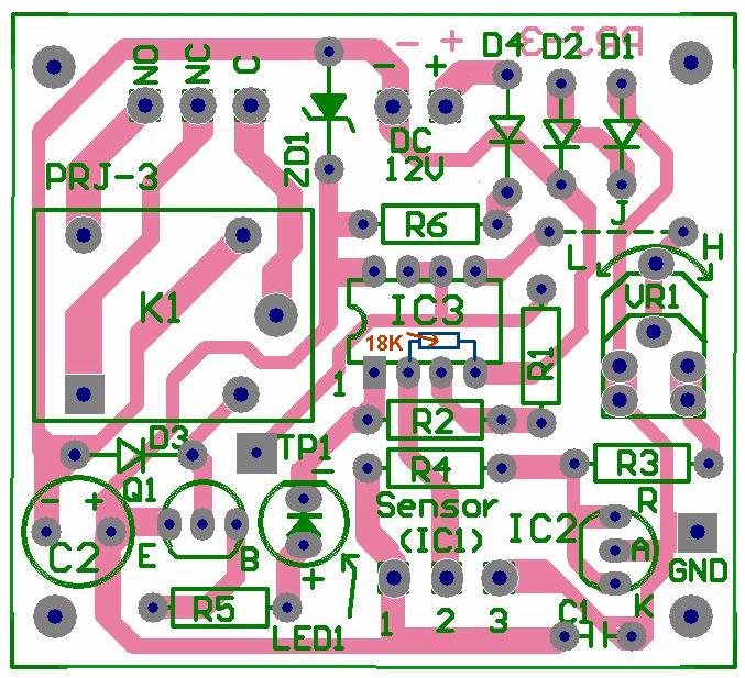
This is an electronic circuit that can be used as automatic temperature control application. The circuit switches a miniature relay ON or OFF according to the temperature detected by the one-chip temperature sensor LM35. When the LM35 detects a temperature higher than the preset level (set by VR1), the relay is actuated. When the temperature falls below the preset temperature, relay is de-energized. The circuit can be powered by any AC or DC 12V supply or battery (100mA min.)
Download : schematic, layout and PCB (pdf)
related search : Electronic circuit project, automatic application, temperauter controller, LM 35 (src)
Most widely spread DCF77 radio-controlled clock receiver are connected computer via the serial port but this electronic project will show you how to make DCF77 radio clock receiver connected via USB using a small 8-pin microcontroller ATtiny45. The project programed with the smart firmware called AVRUSB and AVR-CDC. With this firmware combination, the DCF77 receiver creates a serial port and is fully compatible to old-style true-serial-port ones. No software adaption is necessary.
Download : schematic and Firmwire
tags : Microcontroller AVR Project, radio-controlled clock receiver, USB (src)
This is a simple version of Card Reader. Why? because this Magnetic Card Reader only in read only environment. It only read the information stored in magnetic card. The purpose of the project is used as card debugger. There are three main part in this project :
- A reader to capture digital characters from the card
- A RISC microcontroller to store data and check for errors
- A display to relay the magstripe contents to the viewer
As processor it use microcontroller AVR ATtiny 2313. For Reader it uses Panasonic ZU-M2121S451 Reader. and for display use LCD 16x2.
The Magstripe (Track 2) Reader project can be used to view numerics stored a magnetic data card. Although there is no writeback ability, the device is very useful as a card debugger. The treatise will use an LCD character display to relay this data to the user. The circuit uses an AVR microcontroller and can modified to work with similar RISC controllers.
Although the card reader can't write back to magnetic card, I guess this is a one of good reference to learn how card reader work. For download the reference clik here (zip file)or visit this link
Thanks to Brady Mayes for great card reader based on microcontroller.


